Porcelain Insulator News
by Elton Gish
Reprinted from "Crown Jewels of the Wire", January 1997, page 5
HAROLD H. BROWN INSULATOR
In early 1993, Otto Boll donated to my Research Files a thick notebook about
the development of the Harold H. Brown insulator (Locke insulators with metal
crown) and a porcelain insulator patent model that represents one of two styles
claimed in Mr. Brown's original patent application. Note that I did not say the
insulator represented Mr. Brown's patent. Furthermore, most of us thought that
the various specimens of Locke metal crown insulator were based on the Brown
patent which isn't exactly true -- more on that later in this article. I promised
Otto an article on the Brown insulator, and it has been long coming. I hope that
I can do it justice and get the facts correct. There is too much information in
the notebook to include in one PIN article, and much of it is too technical for
general interest anyway. It has been a struggle wading through all of it, and I
hope that I recorded the story correctly and make it fairly easy for you to
follow.
Otto worked in the engineering department of the Wisconsin Michigan
Power Co. at Appleton, WI. Otto's boss in the late 1930's and early 1940's was
Harold H. Brown, Chief Electrical Engineer. The WMP Co. served the east central
part of Wisconsin and the central part of the Upper Peninsula of Michigan. Otto
said, "The somewhat isolated areas (especially in Michigan) made it
necessary to limit power line interference to a minimum to enhance radio
reception in the areas. I worked for Mr. Brown during the later 1930's and can
remember working on a project to get an AM radio station moved from Iron
Mountain (which had two stations) to Iron River, MI. We were having many radio
interference problems with a 69 Kv line going through town."
During the
1930's and 1940's, all companies manufacturing high voltage insulators were
experimenting with ways to solve the radio frequency interference (RFI) problems cause by the corona effect
around the insulator crown where the conductor is attached to the insulator. AM
radios were particularly susceptible to the problem of spurious radio signals,
and, as Otto pointed out, the problem was very acute in areas where radio
signals were weak (at the edge of reception areas). RFI was rapidly becoming a
problem during this time period because many new high voltage lines were being
installed in an effort to supply every home in America with electrical power
(remember the REA act which brought electrical power to rural areas),
transmission voltages were increasing, and the number of radios in use was
rapidly growing as many homeowners soon purchased a radio after receiving
electrical power.
RFI is caused by electrical corona. The corona effect is the result of an
electrical imbalance at the point of contact between the conductor and
insulator. For pin-type insulators the corona generally first forms between the
tie-wire and the porcelain insulator. The electrical flux flow through the air
gap between the porcelain and the tie-wire is the largest contributing factor
for RFI. In most cases, the RFI disturbance is created at voltages less than the
voltage the insulator normally operates. The noise created is audible to the
human ear and also with radio receivers. The radio frequencies generated range
from low to high frequencies so all AM radio channels are affected. About the
same time that the audible noise and RFI disturbance is detected, a glow or
corona formation is noticeable in darkness. Insulators not designed to reduce
RFI may produce RFI at a potential as low as 6 Kv for a 20 Kv insulator.
Ways of
preventing or reducing RFI concern making the crown more conductive. Originally
the tie-wire was wrapped several times around the crown. Thin porcelain shells
reduce RFI because they increase the electrical flux through the porcelain. For
example, two-part insulators have a lower RFI level than three-part insulators
designed for the same voltage service because the overall porcelain thickness is
greater for a three-part insulator. Various metallic coatings on both the crown
and inside the pinhole (or use of metal thimbles) increase the electrical flux
and decrease the RFI effect. Sprayed on metal coatings and fired on metal
coatings on porcelain insulators where the edge of the coating is thin show a
small amount of corona occasionally on the outer edge of the metal. This small
glow of corona represents a very little RFI effect. However, for thicker
coatings that present an abrupt edge above the porcelain, additional
improvement in RFI was experienced where a groove was cut into the porcelain so
the metal coating ran flush against the edge of the groove in the porcelain. When metal coatings were
used, the tie-wire was wrapped several times around the crown to prevent a loose
tie-wire or conductor from rubbing through the coating. Copper conductors and
tie-wires should always be used with a copper coating and aluminum for aluminum
coatings.
Mr. Brown conceived of a novel design to reduce the corona effect by
using a metal crown on a porcelain insulator. He conducted numerous day and
night RFI tests beginning on December 18, 1930. Over seventy recorded tests were
made with different insulator styles and arrangements of insulators and hardware
before the merits of balanced stress was considered and new designs
incorporating this concept were experimentally tried in the laboratory. On
February 2, 1931, a design using a turned bronze cap and standard lineman's tie
was tested. On February 20, 1931, the sphere ball design with metal crown was
tested (see photograph 1). The first test was not completely successful and
changes were made.

Photo 1: First experimental sphere ball design with bronze crown.
Next a more typical design was employed which had a skirt, petticoat, and
threaded pinhole. Two designs were tested. One design used a bronze crown
inserted in the top of the porcelain shell and the other design used a bronze
crown with a convex base that fit over the top of the porcelain shell and into a
recessed area (see photograph 2 and 3).

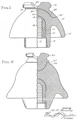
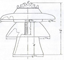
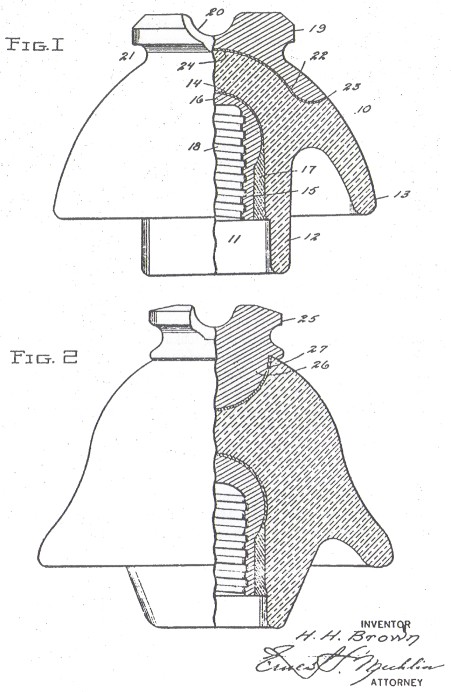
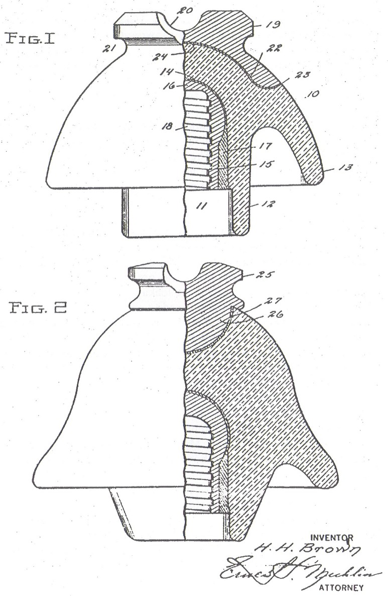
Photo 2: Convex-shaped bronze metal crown cemented into recess cut
into the
top surface of the insulator (see Figure 1).
This design is one covered by the
H. H. Brown patent.
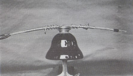
Photo 3: Plug-shaped bronze metal crown (see Figure 2).
Figures 1 and 2 were submitted with the original patent application. Only
Figure 1 was used when the patent was granted. Figure 2 is the design of the
Brown patent model donated by Otto Boll.
Medium Image (74 Kb)
Large Image (187 Kb)
The Locke Insulator Corp. was interested in the work going on at the
Wisconsin Michigan Power Co. and followed their efforts to develop a porcelain
insulator that would have lower RFI properties. On February 25, 1931,
representatives from Locke reviewed preliminary sketches of some of Mr. Brown's
ideas for a new insulator. Another meeting on March 4, 1931, with another Locke
representative led to more sketches showing two more of Mr. Brown's ideas. One
design had a metal crown inserted into a hole in the top of the porcelain body
and the other design had a metal crown with convex-shaped base which allowed it
to be cemented into a recess cut into the top of the porcelain body. The metal
crown insert design seemed more favorable and the final drawing embodying this
feature was completed on March 18, 1931 (Figure 2). The final drawing for the
convex crown design was completed on April 8, 1931 (Figure 1). The drawings were
sent to Locke in Baltimore, and prototypes were made and tested. Tests were
performed on the same two prototypes (Figures 1 and 2) on June 29, 1931, in
Appleton, WI and on August 15, 1931, at the Locke factory in Baltimore.
Test
results at the two laboratories were inconsistent and questions of cement
degradation were brought up. A bakelite material was used for the cement. The
original experimental ball design showed better results but it was not practical
to use for wet weather (no petticoats to extend the leakage distance).
Additional tests were performed which continued to show a large variation. It
was finally concluded that the RFI characteristics are difficult to determine at
the lower voltages for which the insulators would be used due to the effects of
humidity and the sensitivity of their electrical instruments - the human ear. In
all cases the two styles of insulator were acceptable and offered improvement in
RFI. The style with the convex crown (Figure 1) offered the lowest RFI
improvement, and the style with the metal crown inserted in the top offered the
best RFI improvement.
On November 6, 1931, Mr. Harold H. Brown filed a patent
application on the two styles shown in Figures 1 and 2. On March 29, 1932,
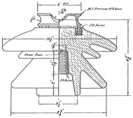
Wisconsin Michigan Power Co. received a response from their inquiry into two
insulator styles Jeffery-Dewitt Insulator Co. was making which had a malleable
metal crown cemented (J-D alloy cement) into the top of their standard one-piece
insulator (see illustration of J-D styles E-1056 and E-1032). These insulators
were cast like the other one-piece J-D styles but without the standard crown.
J-D set the selling price at not much more than their standard insulator. This
information was forwarded to Locke's attorneys who assured them that there would be no interference with the Brown
patent. This meant the Locke could not make a patent interference claim against
J-D and prevent them from marketing their insulators. To make matters worse,
Locke could not manufacture the Brown insulators at a modest increase in cost
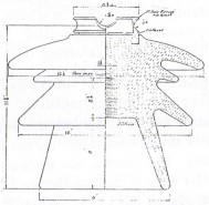
over their standard styles. The drawing for Locke's first insulator using the
Brown design was made on May 9, 1932 and is shown here from Locke drawing No.
U-74385. This style is essentially Locke No. 23526 in their 1941 catalog which
has been assigned M-3650. Note that the metal crown design for drawing No. U-74385 was quite different from anything that Brown had either experimented with
or shown in his patent application and also different from that shown in their
1941 catalog.
 |
 |
|
Jeffery-Dewitt styles E-1056 (left) for 45 Kv and
E-1032 (right) for 66 Kv
drawing dated in early 1932. |
First insert-type Locke style shown in
drawing No. U-74385 dated May 9, 1932.
It is curious that Locke did not obtain legal assignment of the Brown patent
until they received notice from the patent office on June 21, 1934, that the
patent would be allowed. Mr. Brown made the legal assignment of patent rights to
Locke on October 5, 1934. Note that Mr. Brown's patent application was changed
by the patent office to exclude the plug-type design represented in Figure 2.
The final patent No. 1,988,369 was granted on January 15, 1935 for the
convex-shaped metal crown (Figure 1). Evidently no patent application was filed
on Figure 2. All Locke's lawyers had to say about the matter was:
"You will note that there is but one figure of drawing and of course
only one form of the invention disclosed. When we filed this case it had two
forms, one in which the curved surfaces are concentric [convex-shaped crown], as
in the patent, and the other in which the curved surfaces were opposed instead
of parallel. It was impossible to draw an allowable claim covering both forms
and it was therefore necessary to make an election, which we did as you will
see."
Obviously Locke's lawyers worked on the matter a considerable length of time
because the patent took more than three years to complete. Mr. Brown was
undoubtedly very proud of his invention. His wife, Eleanora Brown (age 89),
wrote in a letter to Otto Boll on March 18, 1993, "When Harold and I would
drive, especially in Upper Michigan and Canada, Harold would point out
"his" insulators. What surprised me was that after his death, we found
none of these insulators."
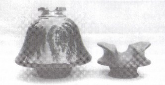
Brown patent model based on design shown in the original patent application
(Figure 2) but not in the final patent. The bronze metal crown is cemented in a
hole formed in the top of the insulator. On the right is a cast iron crown used
on the Locke multipart insert-type insulators.
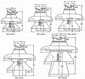
Five multipart insert-type insulators in the 1941 Locke catalog.
Locke only used the Brown patent for multipart insulators, and they were
referred to as "multipart insert-type, noiseless". The only Locke
catalog that carried a line of the insert-type noiseless insulators was dated
April 1, 1941. Five styles were illustrated and shown here.
Locke No. 23522
|
M-2343
|
7.5 - 6.5 - 3 x 7
|
15 Kv
|
(1 known)
|
|
Locke No. 23523
|
M-2639
|
9 - 7 3 x 8.5
|
22 Kv
|
(unreported)
|
|
Locke No. 23524
|
M-2770
|
10.5 - 8 - 4 x 9
|
30 Kv
|
(unreported)
|
Locke No. 23525
|
M-2961
|
12 - 9.5 - 5 x 11
|
30 Kv
|
(unreported)
|
Locke
No. 23526
|
M-3650
|
13.5 - 11 - 7.5 x 13.5
|
44 Kv
|
(unreported)
|
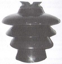
Two other styles have been discovered. In each case the five-digit catalog
number is shown under the incuse marking like this:
LOCKE
23529
|
Locke No. 23527 |
M-4343 |
14 - 12 - 10 - 8 x 14 |
(1 known) |
|
Locke No. 23529 |
M-3245 |
10 - 8 - 5.5 x 11 |
(4 known) |
Note the catalog number 23529 does not follow the standard size category. I
would guess that M-3245 was manufactured after the 1941 catalog offering and
perhaps for a higher voltage service than M-2770 was designed for. M-3245 was
reported by Rick Soller (NIA #2958) who obtained it from Otto Boll. Jeff
Kaminski (NIA #3582) sent the nice photograph of this unusual style. M-4343 was reported in
January 1993 by Steve Jones (NIA #5426) and Jeff Kaminski. Four specimens of
M-4343 have been reported. Note that four of the five styles cataloged in 1941
have NOT been reported. There must be some of these out there somewhere just
waiting for one of you to bring it home. By the way, the 1941 Locke catalog
shows a photograph of a line using the insert-type insulators in West Virginia
(no town given). Following is a quote from the Locke catalog:
"The original noiseless pin-type insulator was developed and introduced
by the Locke Insulator Corporation in 1931 and won immediate acceptance. It
definitely corrected what in many cases had become an exceedingly acute
annoyance and relieved operators of the necessity of using the temporary and
costly expedients which until then had been the only corrective measures
available.
After ten years of service this design has amply proved itself. The
original installation is still 100 per cent intact and still absolutely
noiseless as are all subsequent installations.
Even when installed within a few
feet of highly sensitive sets Locke insert-type Noiseless insulators cannot
cause interference nor do loose tie wires have any effect on their noise
influence characteristics."

Locke M-3245
(10 - 8 - 5.5 x 11) |
Locke M-4343
(14 - 11.5 - 9.5 - 7.5 x 15) |
| 
)
)
)
)
)
)
)
)
)
)